XCrySDen tessellate the
isosurface from a 3D grid of values. This 3D grid of values span
some box, and beside the isosurface display it is also possible to
render the contours and colorplanes on the slices of three basal
planes of the grid-box (what is really meant by this will be
explained below), namely, on AB, AC, and BC planes.
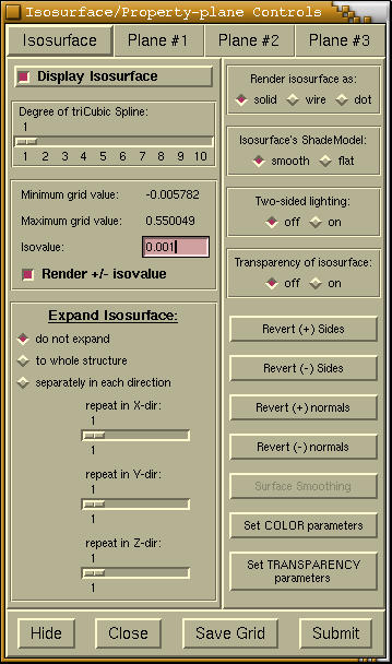
The isosurface display requires a lot of parameters to be
specified. Of course
XCrySDen sets those parameters to
some default values, but nevertheless these defaults are rarely
sufficient for a good quality display of isosurface. Therefore when
rendering the isosurface the
Isosurface/Property-plane
Controls window appear shown below.
Important: as there are many items on the below window,
the figure was made interactive in order to
facilitate easier explanation of items functions. Simply
mouse-click appropriate item (widget) to get its
explanation.
This radiobutton toggles the display of isosurface.
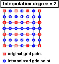
Allows to interpolated the 3D grid values by tri-cubic spline
interpolation. The term
degree determines how many
additional points will be interpolated. The value of 1 means
no-interpolation, while the value of 2 means calculate a middle
points between two sequential points. Here this is shown
graphically for 2D example:
These two labels displays the minimum and maximum grid values. The
specified isolevel should be in this range.
In this entry one specifies the isovalue (isolevel) for the
isosurface. When this value is changes the
[Submit] button should be pressed to load the
newly specified value and to update the display of the isosurface.
Toggles the display of isosurface with
-isovalue
value. An example: when displaying the isosurface of a molecular
orbital, then it is a good idea to display both positive and
negative valued isosurface (for example the -0.02/0.02
sqrt(BOHR^3/electrons)). By default the positive isosurface is
rendered in red, while negative in blue. If one does not see these
colors, then she/he should play with the
[Revert (+) Sides],
[Revert (-) Sides],
[Revert (+) Normals],
[Revert
(-) Normals] buttons. The functions of these buttons is
explained bellow.
The radiobuttons and scales on this frame only appears for periodic
structures. The widgets allows to control the display of the
periodic replicas of the isosurface. I hope these widgets are
self-explanatory and we can try them out by testing.
Warning:
- press the [Submit] button to
update new expand setting.
- The isosurface can be expanded just to the size of the
currently displayed structure. Hence use the Modify-->Number of units drawn menu to
change the number of displayed unit cells.
Controls the display-style of the isosurface. Currently the solid,
wire and dot display styles are implemented.
Controls the shading of the isosurface, which is either smooth or
flat.
Toggles the display of two-sided lighting. By default two-sided
lighting is disabled. This feature needs some more explanation. Any
surface has two sides, which we will call the front and back sides.
Now if we render the isosurface of molecular charge density, then
this isosurface will be closed and only one side will be visible
(let's say front side). Hence we can disable the lighting of the
back side in order to gain the rendering performance (i.e. speed).
However it is very common to get an open surface for the
crystalline structures, since we are only rendering a part of it,
namely, some number of unit cells. To correctly render such a case,
the two-sided lighting should be enabled, otherwise the
illumination of the back-side will be incorrect. Furthermore, the
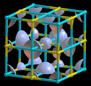
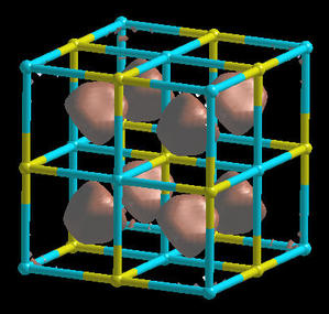
choice of the front and back sides can be quite arbitrary. Why? Let
us take a look of the charge density of the TiC crystal at two
different isovalues, that differs for the factor of 10.
The isosurface on the right figure is rendered at 10 times lower
isovalue with respect to the left one. We can realize that what we
would normally define as front-side is different for left an right
figure. Normally I would define the blue-surface on the left figure
as a front-side and a red-surface on the right as the front-side.
Therefore, due to this arbitrariness of the choice of the front
side,
XCrySDen provide
[Revert (+) Sides] and
[Revert (-) Sides] buttons,
which swaps the front and back sides. The (+) button is meant for
isovalue isosurfaces, while (-) button for
-isovalue isosurfaces. Furthermore, there are also
[Revert (+) Normals] and
[Revert (-) Normals]
buttons. Their function is the following: sometimes the
illumination of the isosurface looks as from-the-back. In these
case revert the normals to get the correct from-the-front
illumination.
Toggles the transparency of isosurface.
Sometimes the isosurface is not illuminated correctly. Hence
several command buttons exist to improve upon that.
Swaps the front and back sides of the
isovalue (i.e.
(+)) isosurface. See also the discussion on
two-sided lighting.
Swaps the front and back sides of the
-isovalue (i.e.
(-)) isosurface. See also the discussion on
two-sided lighting.
Reverts the isosurface normals (i.e.
nnew = -
nold) of the
isovalue (i.e. (+)) isosurface. See also the
discussion on
two-sided lighting.
Reverts the isosurface normals (i.e.
nnew = -
nold) of the
-isovalue (i.e. (-)) isosurface. See also the
discussion on
two-sided lighting.
Here we can set the color parameters for the isosurface. When this
button is pressed, the following window appears:
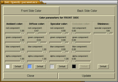
In this window we see a whole bunch of parameters, but this is how
it is. To get an extensive description of all of these refer to
some OpenGL guide. There should be plenty sides on the WEB, where
the lighting is explained. Here we just shortly summaries.
At the top of the window the [Front Side Color] and
[Back Side Color] tabs are located. Pressing one of them
displays the values of corresponding parameters.
At the bottom we see the [Close] and [Update]
buttons. The first one closes the window, while the latter update
the current color setting. It is mandatory to press this button to
load the new setting.
In the middle we the the Ambient, Diffuse, Specular and
Shininess parameters.
| Ambient color |
this is the color that the object inherits
from the environment. For example an object will appear in
different color under day light or in some room with some
artificial color of light.
|
| Diffuse color |
These are the most important parameters, since
the color of the isosurface is mostly determined by them. The
red/green/blue determines the color, while alpha is used for
transparency.
|
| Specular color & Shininess |
Determine the appearance (i.e. shinnines) of
the isosurface. For example specifying the specular color as white
(1.0,1.0,1.0) and putting the specular exponent to large value
(app. 100) will make the isosurface to appear like a metal surface,
while specifying low specular color (0.1,0.1,0.1) will make the
isosurface to appear like a paper.
|
Please note that there are two sets of color parameters, one for
non-transparent isosurface and one for transparent isosurface. If
we press the [Set COLOR parameters] button then we will edit
the color parameters for non-transparent mode. To edit the color
parameters for transparent mode press the [Set TRANSPARENCY
parameters] button.
Here we can set the transparency and color parameters for the
transparent mode of the isosurface. When this button is pressed,
the following window appears:
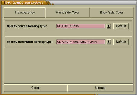
At the top of the window the
[Transparency],
[Front Side
Color], and
[Back Side Color] tabs are located. The
meaning of the last two is the same as the ones appearing for
Set Color parameters task. Pressing the first
button displays the transparency parameters. Refer to the any
OpenGL guide for the meaning of these parameters.
At the bottom we see the [Close] and [Update]
buttons. The first one closes the window, while the latter update
the current color setting. It is mandatory to press this button to
load the new setting.
At the bottom of
Isosurface/Property-plane Controls the
[Hide]/
[Close]/
[Save Grid]/
[Submit]
buttons are located. The function of these buttons is as follows:
| [Hide] |
Hides the Isosurface/Property-plane
Controls window. Hiding means that window is iconified, i.e.
the window disappears and its icon appears on XCrySDen main render window.
Pressing the icon pop-ups the window
|
| [Close] |
Closes the window. The 3D grid data will be
flushed (cleared).
|
| [Save Grid] |
Saves the 3D grid data in XSF format.
|
| [Submit] |
Loads new isosurface parameters and renders an
updated isosurface.
|

![[Figure]](img/xcrysden-picture-small-new.jpg)